Tuesday, November 24, 2009

Baseplate Ankle Insets & 2nd Plate


On the bottom picture, You can see the Ankle Insets being glued into place.
This area provides a clearing for the outer legs to pass the body if your
building your droid to stand on 2 feet and then move to the 3 leg position.
This movement is known as the 2-3-2.

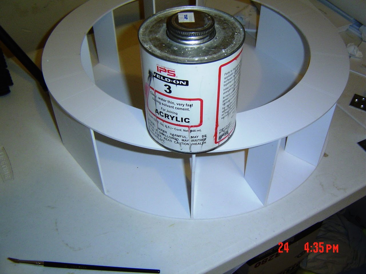
The next picture shows the 2nd ring being glued into position.
There's 10 spots that have to be glued and the way I did this one
is to lay the plate on top of the verticals and align the plate as
best as you can with the scribed marks facing up.
Glue 1 vertical then after it dries glue another vertical across
from the one you just glued. Make sure you pay close attention to all
the scribes as you work around the plate.
I left the Ankle Inserts as the last parts that get glued after the
other eight.
I also used the Weldon can as a weight to keep the verticals in place as I glued
them.

Monday, November 23, 2009

Baseplate Verticals


In the bottom picture it shows how you start gluing the 1st set of verticals to the bottom plate.
We bought some small angle brackets to help support the plate as the glue starts
to set, We're also using a small square to check the parts as we glue.

As you look at the pictures from bottom to top, You can see how the process gets
repeated 8 times for a total of 8 verticals.
We now have 2 Ankle Insets to glue to the bottom plate.
These are lined up with the straight edges on the bottom plate.
When you cut the bottom plate you will have 2 small parts left over and these
get glued to the Ankle Insets and they provide support for the skins.

Sunday, November 22, 2009

Frame Cutting

We spent most of the day cutting out more frame parts.
I'm not going to post pictures of the parts being cut,
Because the blueprints do a very good job of showing how
to cut the parts.
I will be showing the parts cut with the blueprint still attached
to the part and how the construction is done.
So far, We have used 1 4x8 sheet of Styrene to build the frame.
1 Sheet of 3mm Styrene cost $32.00 and you will have some
leftovers for small parts.
More to come :o)

Saturday, November 21, 2009

Bottom plate

Once you bond your blueprint to the Styrene,
You can get ready for the routing.
If you notice, There are 3 small holes in the center of the circle.
These are marked on the blueprint and I used a 1/8 drill bit to mark
the location of each.
The outer 2 holes are for the center leg to mount and the center hole
is your pilot hole for the router pin.
Carefully run the router around the 20x20 inch Styrene plate and you will get your
rough cut using the R9 pin hole.
Then using the 9 pin hole, Run around the plate again and you will get a nice
smooth plate.

Now lightly scribe the lines marked on the blueprint.
These lines will be used as a mark for the vertical plates to be glued.
The solid lines on each side get cut completely off the plate and saved for
a future plate.

Now you can peel the blueprint off the plate and I lightly sand the sides
of the plate, Just to make it nice and clean.


Router Jig

This is the router jig I made to cut the circles.
It's made of 1/4 styrene and you can see in the pictures how I bolted
it to the router.
I also have marked holes in the plate for a pin to keep it in place while
we slide it around on top of the 3mm Styrene.
I made the 1st cut with the R9 hole which is a ruff cut and then
I use the 9 hole for the finish cut.
This gives me a smooth cut all around the 3mm circle.


Sunday, September 13, 2009

R5 Skins


And this is how it looks after cutting.
I only cut the areas where I will have something mounted or a opening for something to open.
When your working the skins you need to decide what will open on your droid.
I will only have one large door opening and the charge port opening.


Since the 3mm (1/8) Styrene has not arrived yet, We decided to work on the skins.
We all took turns using the cutting table and I've got 1 inner skin almost finished.
I went ahead and cut the sides, bottom and top down to the print.
But this is how it looks with the blueprint spray tacked to the styrene.

Once the frame material arrives, I'll have tons of pics to post.

Sunday, September 6, 2009

Ryobi Trimmer

This is the Trimmer I bought at Home Depot for around $80.00.
It's small and compact, So it should be easy to use.
The bottom of the Trimmer has 4 small screws that the large plate mount, But I
plan to use these holes for mounting the Trimmer upside down on a wood surface
to cut the frame circles. You can see the large plate has the same mounting holes.
I won't use the large plate except to get the measurements for mounting.

Once I get the Trimmer setup, I can start cutting my frame.
Everything I'm doing to build this droid is the Dave E. design and
he made a Trimmer setup just like this setup.